Surfacing module
![]() |Surfacing Module
|Surfacing Module
![]() Product Overview
Product Overview![]() Contents
Contents![]() Comparison of Performance
Comparison of Performance![]() Operation Environment and Features
Operation Environment and Features![]() Case Study
Case Study
Surfacing Module
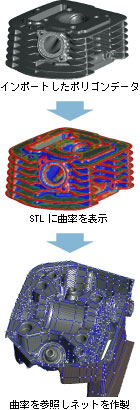
3D CAD is indispensable for manufacturers whose works rely on it.Naturally, they often wish to convert the measured data into CAD. However, it is not theoretically possible to carry out the conversion with a simple process because CAD and measured data have different system of representation and ways of being represented in computers even if they look the same on the monitor. Measured data separately accommodates information about pixel, triangles, and coordinates. Hence, it does not record them as atopologically organized way.
On the other hand, CAD softwares defines the shape of objects, utilizing equations such as NURBS and the data that controlls them, by constructing either the surface of the objects or tge surface plus the filling. If one wants to display or measure measured data that tends to be large, or create CAD by surfacing, not CAD but reverse engineering software such as PoiutMaster is required.
PointMaster can convert polygon data into CAD by pasting "surface" onto the surface of the polygon and output the result as IGES file.
It is tough to make acceptable CAD data.To put it another way,measurement data could finally become CAD file if only time is not a problem although success depends to some extent on the quality and complexisity of the measured data. When structural analysis and design software, and input format are restricted, users sometimes have to spend lots of time to make CAD.
The main feature of PointMaster is that high quality CAD surface can be made facilely by anyone.
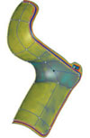
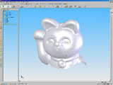
Procedure Overview of CAD Creation of a Object
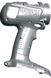
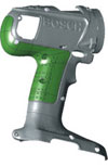
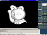
(1)Measured Data
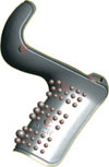
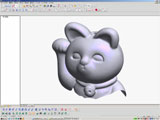
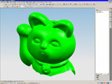
(2)Fraturing to spheres
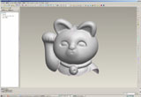
(3)Fixing holes and torn parts of polygon data
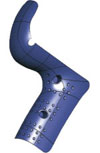
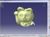
(4)Extracting silhoette of the object
(5)CAD plane is pasted
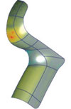
(6)Errors between measured data and pasted surface are checked any time.
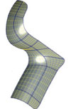
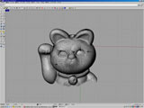
(7)Checking the quality of planes and connections by contour linef
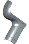
(8)Expanding the surfac
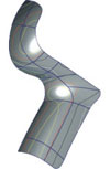
(9)近似形状をスケッチした自由曲面を組み合わせて、トリミングします。
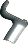
(10)Brepで記述された最終形状
PointMasterによるCADリンク
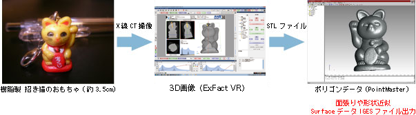
![]() SurfaceデータをIGESファイルとして出力
SurfaceデータをIGESファイルとして出力
![]() Transferable 3D CAD softwares of IGES files
Transferable 3D CAD softwares of IGES files
Following 3D CAD software is available that can futher process the data output from PointMaster.
SolidWorks 2004
(SolidWorks Corporation, USA)
thinkID-DesignXpressions
(think3, USA)
CATIA Version 5 Release 13
(Dassault Systems, Fr)
Rhinoceros
(McNeel, USA)
I-deas 11 NX Series
(UGS PLM Solutions, USA)
Pro/ENGINEER Wildfire 2.0
(PTC, USA)
NX3
(UGS PLM Solutions, USA)